Next step for the modeling of our PythonPart “Reinforced Concrete Column”, today let’s see how to configure the anchors of our 3D object.
By anchoring I am particularly thinking of 2 types :
- altimetry management ;
- the insertion point in plan view.
1) GUI Script
-
Altimetry
Much more than a simple 3D object positioned without any intelligence, the Allplan API allows us to automatically hook our PythonPart to the levels present in the building structure.
To do this, we will complete our previously used “Height” variable ; for the record, we had set up a “Length” field, a generic type for entering a length.
Indeed, to allow us to define a reference at a level, we will first set up the dialog box used by the standard architectural elements :
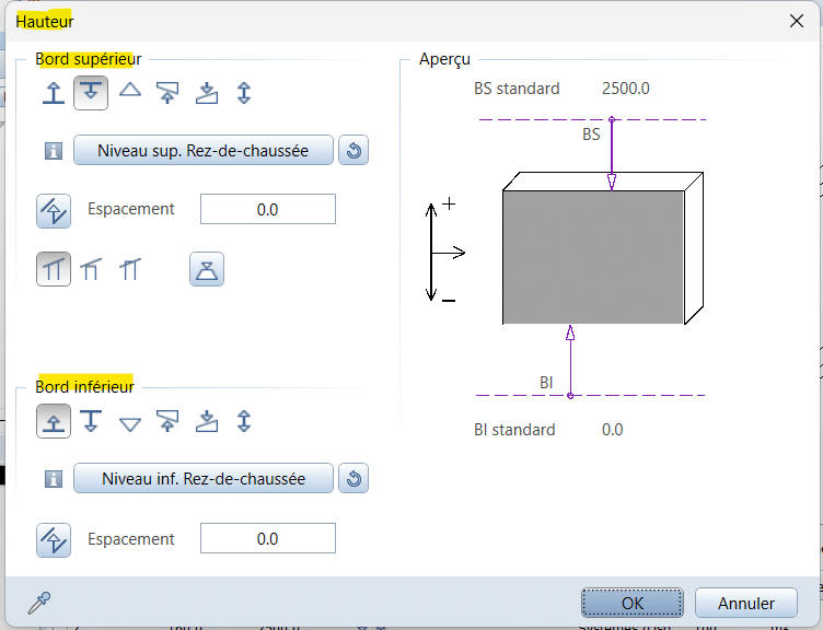
Please note :
There are 3 ways to define a reference to a plane :
- top edge entry ;
- bottom edge entry ;
- both.
We will choose this last hypothesis.
<Parameter>
<Name>PlaneReferences</Name>
<Text> </Text>
<Value></Value>
<ValueType>PlaneReferences</ValueType>
<ValueDialog>PlaneReferences</ValueDialog>
</Parameter>
In order to obtain a better user experience, we will link our Height field to this PlaneReferences by adding a new tag named Constraint.
In this way Allplan will automatically calculate and display the absolute height of our object.
Here is the syntax :
<Parameter>
<Name>ColumnHeight</Name>
<Text>Hauteur</Text>
<FontFaceCode>4</FontFaceCode>
<Value>-1</Value>
<ValueType>Length</ValueType>
<Constraint>PlaneReferences</Constraint>
</Parameter>
<Parameter>
<Name>PlaneReferences</Name>
<Text> </Text>
<Value></Value>
<ValueType>PlaneReferences</ValueType>
<ValueDialog>PlaneReferences</ValueDialog>
<Constraint>ColumnHeight</Constraint>
</Parameter>
Please note : this tag “Constraint” was added in the 2 fields in order to create a bidirectional connection
Back in Allplan, I obtain :

If I modify the height as follows :
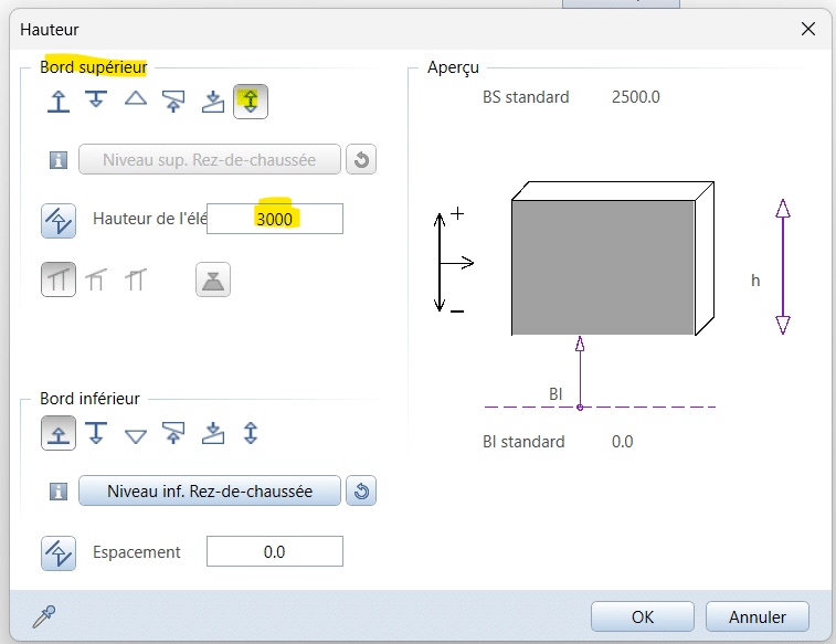
the value updates :

Inversely, when I change my value in the palette :

the fields in the dialog box are correctly updated :
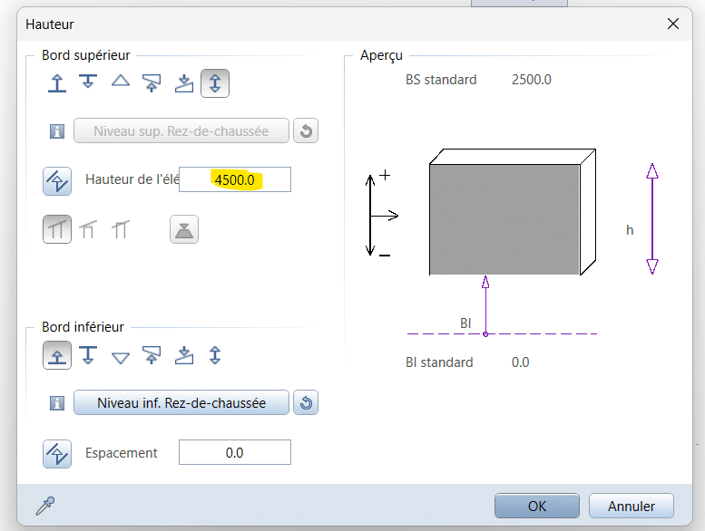
-
Insertion Point
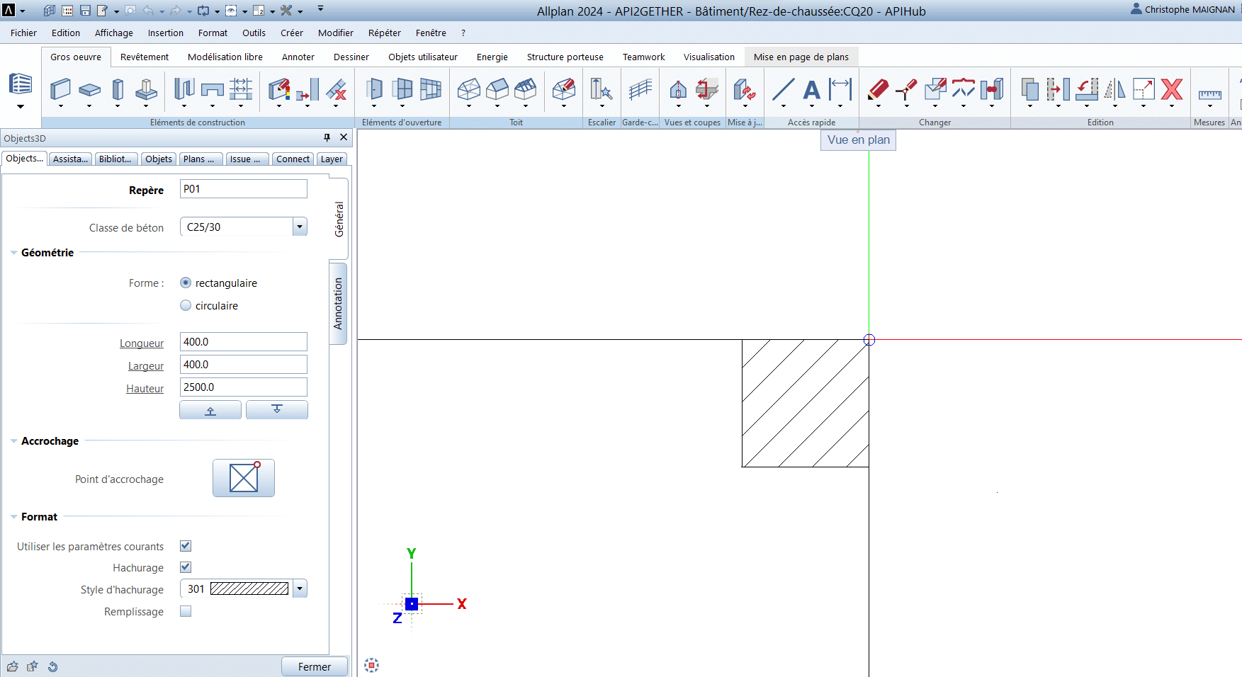
In the first chapter of this example, we set up a column that could be rectangular or circular.
With the parameters entered we obtain :
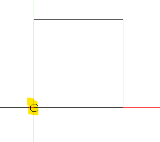
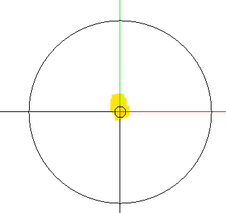
Following the same logic as for elevation, we will replicate the native behavior of Allplan with architectural elements, specifically the columns.
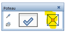
I’ll create a new Expander dedicated to this function :
<Parameter>
<Name>AttachmentExpander</Name>
<Text>Accrochage</Text>
<ValueType>Expander</ValueType>
</Parameter>
then I add the following fields :
<Parameter>
<Name>AttachmentPointButtonRow</Name>
<Text>Point d’accrochage</Text>
<ValueType>Row</ValueType>
<Parameter>
<Name>AttachmentPoint</Name>
<Text>Attachment point index</Text>
<Value>5</Value>
<ValueType>RefPointButton</ValueType>
</Parameter>
</Parameter>
Please note :
- I place my button in a Row and I complete the text that will be displayed in Allplan ;
- with 5 as the default Value, we propose a center anchor.
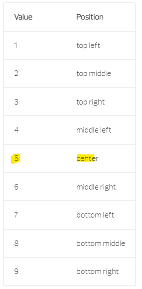
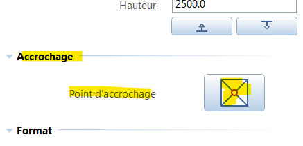
Back in Allplan, I obtain :
Here is the complete file :
2) Main Script
I start by completing my list of imports :
import NemAll_Python_ArchElements as ArchElements
-
Fonction create_element
Then I go to the create_element function to complete the list of retrieved information :
attach_point = build_ele.AttachmentPoint.value
plane_ref: ArchElements.PlaneReferences = build_ele.PlaneReferences.value
Next I create a new variable to get the bottom level of my object :
column_bottom = plane_ref.GetAbsBottomElevation()
This level, along with the height (column_height), allows us to model our object.
-
Class Objects3D
I will complete my parent class Objects3D to integrate the 3 anchor values (X, Y, and Z):
class Objects3D:
def __init__(self, object_prop, attach_point, column_bottom):
self.object_prop = object_prop
self.geo = None
self.attach_point = attach_point
self.x_offset = 0
self.y_offset = 0
self.z_offset = column_bottom
Please note : I store the reference point separately and leave the X and Y offsets at 0 by default because the calculation will depend on the shape of the column.
I’m preparing my future attachment_point function to calculate this offset :
def attachment_point(self):pass
-
Class Cuboid
I move to my child class Cuboid and complete it :
class Cuboid(Objects3D):
def __init__(self, object_prop, attach_point, column_bottom, column_length, column_thick, column_height):
Objects3D.__init__(self, object_prop, attach_point, column_bottom)
self.column_length = column_length
self.column_thick = column_thick
self.column_height = column_height
self.name_dim = f”{round(column_length / 10)}x{round(column_thick / 10)}”
self.placement_pt = self.attachment_point()
To fully understand the placement in plan view, it’s necessary to keep in mind the values returned by our AttachmentPoint, which I remind here :

By default, our rectangular column is placed from the lower-left corner, so :
- in X
- values on the left (1, 4, 7) are ignored ;
- values in the middle (2, 5, 8) will result in an offset equal to half of the length ;
- values on the right (3, 6, 9) induce an offset equal to the length.
- in Y
- values at the top (1, 2, 3) impose an offset equal to the thickness ;
- values in the middle (4, 5, 6) will result in an offset equal to half of the thickness ;
- values at the bottom (7, 8, 9) are ignored.
In Python, I translate this informations with the following two conditions :
def attachment_point(self):
if self.attach_point in {2, 5, 8}:
self.x_offset = -self.column_length / 2
elif self.attach_point in {3, 6, 9}:
self.x_offset = -self.column_length
if self.attach_point in {1, 2, 3}:
self.y_offset = -self.column_thick
elif self.attach_point in {4, 5, 6}:
self.y_offset = -self.column_thick / 2
placement_pt = Geometry.Point3D(self.x_offset, self.y_offset, self.z_offset)
return placement_pt
Please note : I concatenate the result into a 3D point, which will be returned by the function.
-
Class Cylinder
Same logic as before, but this time we start from a central point.
So, we get :
class Cylinder(Objects3D):
def __init__(self, object_prop, attach_point, column_bottom, column_rad, column_height):
Objects3D.__init__(self, object_prop, attach_point, column_bottom)
self.column_radius = column_rad
self.column_height = column_height
self.name_dim = f”Ø{round(column_rad / 10)}”
self.placement_pt = self.attachment_point()
For the calculation:
- in X,
- values on the left (1, 4, 7) will result in an offset equal to the radius ;
- values in the center (2, 5, 8) are ignored ;
- values on the right (3, 6, 9) induce an offset equal to the radius.
- in Y
- values at the top (1, 2, 3) impose an offset equal to the radius ;
- values in the center (4, 5, 6) are ignored ;
- values at the bottom (7, 8, 9) will result in an offset equal to the radius.
Here is the function :
def attachment_point(self):
if self.attach_point in {1, 4, 7}:
self.x_offset = self.column_radius
elif self.attach_point in {3, 6, 9}:
self.x_offset = -self.column_radius
if self.attach_point in {1, 2, 3}:
self.y_offset = -self.column_radius
elif self.attach_point in {7, 8, 9}:
self.y_offset = self.column_radius
placement_pt = Geometry.Point3D(self.x_offset, self.y_offset, self.z_offset)
return placement_pt
-
Function create_element
Back in create_element, I complete the call to my classes with the new arguments :
# Create 3D object
if choice == “rectangle”:
my_column = Cuboid(com_prop, attach_point, column_bottom, column_length, column_thickness, column_height)
else:
my_column = Cylinder(com_prop, attach_point, column_bottom, column_radius, column_height)
Next, I will perform a global translation on my PythonPart using a Matrix3D :
# Reference point
placement_mat = Geometry.Matrix3D()
placement_mat.SetTranslation(Geometry.Vector3D(my_column.placement_pt))
# Create the PythonPart
model_ele_list = pyp_util.create_pythonpart(build_ele, placement_mat)
Please note : create_pythonpart takes as its second (optional) argument a placement matrix used for the geometry transformation.
Our PythonPart is correctly affected by my translation, but there is an issue : the various handles do not follow.
We will modify them to take the offset into account :
-
Class Handle
The principle is very simple, I just have to sum my anchor points to the insertion points :
class Handle:
def __init__(self, placement_pt, handle_id, handle_point, ref_point, handle_param_data, handle_move_dir, handle_info_text):
self.handle_id = handle_id
self.handle_point = placement_pt + handle_point
self.ref_point = placement_pt + ref_point
self.handle_param_data = handle_param_data
self.handle_move_dir = handle_move_dir
self.handle_info_text = handle_info_text
I make sure to pass the anchor point during the construction of handles for the rectangular shape :
self.handles_prop = [Handle(self.placement_pt,
“ColumnLengthHandle”,
Geometry.Point3D(self.column_length, 0, 0),
Geometry.Point3D(),
“ColumnLength“,
HandleDirection.X_DIR,
“Longueur”
),
Handle(self.placement_pt,
“ColumnThickHandle”,
Geometry.Point3D(self.column_length, self.column_thick, 0),
Geometry.Point3D(self.column_length, 0, 0),
“ColumnThick“,
HandleDirection.Y_DIR,
“Largeur”
),
Handle(self.placement_pt,
“ColumnHeightHandle”,
Geometry.Point3D(0, 0, self.column_height),
Geometry.Point3D(),
“ColumnHeight“,
HandleDirection.Z_DIR,
“Hauteur”
)
]
but also for the circular shape :
self.handles_prop = [Handle(self.placement_pt,
“ColumnRadiusHandle”,
Geometry.Point3D(self.column_radius, 0, 0),
Geometry.Point3D(),
“ColumnRadius“,
HandleDirection.X_DIR,
“Rayon”
),
Handle(self.placement_pt,
“ColumnHeightHandle”,
Geometry.Point3D(0, 0, self.column_height),
Geometry.Point3D(),
“ColumnHeight“,
HandleDirection.Z_DIR,
“Hauteur”
)
]
Here is the complete file :
In this chapter, we have seen how to set up our insertion point and anchoring at different levels, greatly improving the usability of our PythonPart object.

0 Comments